
UsbC charging adapter for legacy gear (non-PD compatible)
Main project requirements and background
-
Some USB devices equipped with an Usb-C port for charging/powering are not compatible with UsbC chargers and require an UsbA-UsbC cable for operation. (some call them "dumb" devices)
-
The situation described above arises from the fact that, according to the USB standard, chargers that transfer power via the USB-C port must first receive a signal via the CC line (see the required voltage value), which will determine what voltage to set on the VCC line. This requirement was introduced to protect the charger from short circuits between VCC and GND, which were always included in earlier USB standards.
-
Chargers with UsbA port have no CC line and transmit 5V by default, unlike UsbC chargers. Thus, the device being charged may not be designed to be powered by UsbC chargers and may not have the CC line necessary, and does not know about this negotiation step to activate the basic 5V charge mode.
-
The signal that the UsbC charger expects to receive for 5V activation is the presence of a 5.1kOhm pull-down resistor on the side of the device being charged, i.e., a resistor (also known as an “Rd” resistor) placed between the CC line and GN,D signaling that a sub-device is connected to the charging adapter and ready to receive power.
-
UsbC cable (male-male connector) has only one CC line, and UsbC female connector located on the charging and charging devices should have two pins, CC1 and CC2. The CC line in the cable connects to one of the two CC1/CC2 pins at a time.
-
In this way, we can install an “intermediary” between the charger and the device being charged that will mimic the missing pull-down resistors so that either of the CC1/CC2 lines will receive the 5V charging activation signal we need.
-
The use of such an adapter is possible with devices that have a realized circuit with resistors on their side.
Creating such an adapter is the goal of this project.
Schematic and finished device
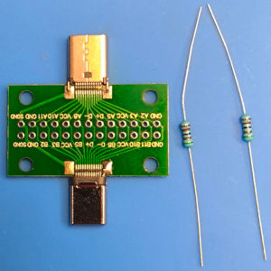
Photo 1

Photo 2
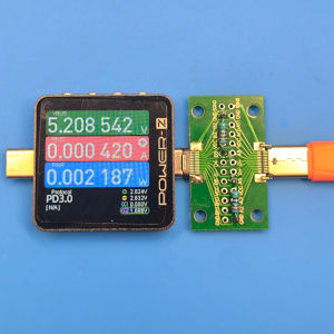
Photo 3
How it works and the components used in the project
The following components are required to build such an adapter (see Photo1):
-
A board with pins(Amazon)(AliExpress) for each pin provided by the male-female UsbC connector. All pins of both connectors are connected to each other, i.e., full electrical compatibility is ensured, and the use of this adapter operates without any limitations with any UsbC cable connected to it, including USB4/Thunderbolt5.
-
Two 5.1kOhm 0.25W resistors (Amazon)(AliExpress) - these resistors will be used as pull-down resistors between CC and GND pins.
-
It is important to install two resistors on each CC pin separately. Connecting both pins and grounding through one resistor to pin GND may work for cables without an e-maker chip (up to 60W), but it will cause problems for more modern cables with an e-maker chip rated 100/240W.
On Photo2, you can see the resistors soldered to the pins labeled B5-GND and A5-GND
On Photo3, you can see the USB tester Power-Z KM003C that doesn't turn on without separate external power if you connect a USB cable to its female port. But thanks to this adapter, which informs the charger about the need to supply power and that there is a device in front of the charger that is requesting power, we can see that the USB-tester turns on, which indicates that this adapter is working correctly.
Please note that the adapter should be connected in the following order Charger->Cable(UsbC-UsbC)->Adapter->Chargeable device. This connection will ensure that only one pull-down resistor is visible to the charger since the UsbC cable uses only one CC line. If you swap the adapter and cable in this chain (which will require you to flip the adapter 180 degrees and connect it directly to the charger), then charging may not occur because the charger will see two pull-down resistors at once, and some power supplies in this configuration refuse to initiate charging.