

USB-C adapter for devices without proper CC signaling
Main project requirements and background
-
Some USB devices with a USB-C port for charging or power do not work with USB-C chargers and require a USB-A - USB-C cable.
-
The reason is related to the USB Type-C connection mechanism: the power source monitors the CC lines and supplies power to VBUS after detecting a sink through an Rd resistor. Until a valid USB-C connection is detected, the source should not supply VBUS.
-
USB-A chargers do not have CC lines, and 5V is normally present on VBUS by default. Therefore, a device that works correctly through a USB-A - USB-C cable may receive no power through a USB-C - USB-C cable if its USB-C receptacle does not have the proper Rd pull-downs on CC1 and CC2.
-
For a Sink, the USB Type-C standard requires a separate Rd resistor on each of CC1 and CC2; the typical Rd value is 5.1 kOhm. The presence of Rd allows the source to detect the connected sink and supply the standard 5V on VBUS.
-
A USB-C - USB-C cable uses one continuous CC channel; the other corresponding contact may be used for VCONN. A USB-C receptacle has CC1 and CC2 contacts, and plug orientation determines which one becomes the active CC line.
-
The adapter therefore emulates a proper USB-C Sink: one 5.1 kOhm Rd resistor is connected between CC1 and GND and another between CC2 and GND. The source can then detect the sink regardless of cable orientation and supply 5V on VBUS.
-
Devices that already have the proper Rd resistors on CC1 and CC2 do not need this adapter.
Creating such an adapter is the goal of this project.
Adapter design
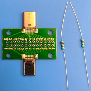
Photo 1

Photo 2
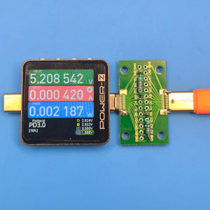
Photo 3
How the adapter works and the components used in the project
The following components are required to build this adapter (see Photo 1):
-
A USB-C male-female breakout board with access to all contacts (Amazon) (AliExpress). In this design, the contacts of the two connectors are connected directly. Compatibility with high-speed modes depends on the quality of the board and signal routing.
-
Two 5.1 kOhm 0.25W resistors (Amazon) (AliExpress) - one Rd between CC1 and GND and one between CC2 and GND.
-
It is important to install one separate resistor on each CC pin. CC1 and CC2 must not be tied together and connected to GND through a single resistor. Depending on cable orientation and type, the inactive contact may be used for VCONN, including to power e-marker electronics or an active cable.
Photo 2 shows the resistors soldered between B5 and GND and between A5 and GND.
Photo 3 shows the Power-Z KM003C USB tester, which does not turn on without separate external power when a USB cable is connected to its female port. With the adapter installed, the source detects Rd on CC, supplies 5V on VBUS, and the tester turns on, confirming that the adapter works correctly.
Connect the adapter in the following order: Charger -> USB-C - USB-C cable -> Adapter -> Powered device. With this arrangement, the source sees Rd through one active CC line in the cable. If the adapter is connected directly to the source before the cable, the source may see Rd on both CC lines at the same time and may not enter the normal Sink connection state.
P.S. Hagibis offers the compact ZJTN05 adapter for the same purpose, so building your own adapter is now optional.